

DONGGUAN ZUFEK PRECISION CO., LTD.
info@zufek.net
DESIGNED FOR RETENTION

Captive Screws
to your drawing.

Retention-oriented screw designs. Share the mating assembly so the retaining features can be reviewed together.

Request a drawing review

Illustrative product family. Final specifications and availability require confirmation.

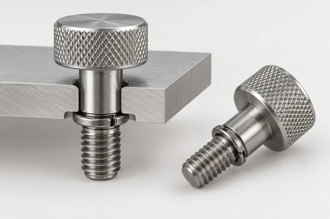
Captive panel screw cutaway illustrating the retaining ring and reduced neck
Captive Screws

Define the part that fits.

A drawing-led review connects your part geometry with its function in the assembly. Identify the requirements that are fixed and the details that can be discussed.

Useful information for review

  • Drawing number, revision and units
  • Head, drive, length and thread specification
  • Critical dimensions and mating-part requirements
  • Material, finish, quantity and inspection records
Use the RFQ checklist ↗

Specification checklist

GeometryDefined by approved drawing
Dimensions & tolerancesState functional and critical features
MaterialSpecify grade or discuss application needs
Surface finishState coating and acceptance requirements
Quantity & timingConfirmed during quotation
VerificationAgree inspection scope before ordering

No universal size, tolerance, material or lead-time claim is implied.

RELATED TECHNICAL READING

Prepare a clearer specification.

DESIGN & DIMENSIONS2 MIN READ

Five questions before specifying a captive screw

Specify a captive screw with its panel, retainer and mating thread. Review installation, released travel and tightened engagement as separate conditions.

By Theo WanRead technical guide →

Before you send your drawing

Can I submit an incomplete drawing?

Yes. Mark the unresolved details and describe the application. Feasibility and pricing depend on confirming the final requirements.

Are material and finish options pre-approved?

No. Available options must be confirmed for your actual part. Read our material selection guide for the information to prepare.

How is quality scope agreed?

Define critical features and documentation needs during review. See our quality planning approach.

Review the captive screw in both service positions

A captive screw belongs to a panel-and-retainer assembly. Check the released position as carefully as the tightened position; usable thread engagement and retained travel answer different questions.

12
Interface sketch — not to scale. Dimensions and acceptance follow the approved assembly drawing.
  1. Released: the screw clears the mating thread while the chosen retaining feature keeps it with the panel.
  2. Tightened: the head seats as intended, the retainer has room to move and the required thread engagement remains available.
  3. Assembly review: provide panel thickness, retaining-hole details, retainer geometry and the installation sequence.

Agree a retention check and a removal/reassembly trial separately from thread gauging. The sketch uses a separate retainer for illustration; the actual retaining arrangement must match the assembly.

Design the retention system together

A reduced shank or retention feature must work with the panel and retaining component. Provide panel thickness, retaining-hole geometry, mating thread and assembly sequence. The screw profile alone cannot establish whether the installed fastener remains captive in every service position.

Check travel in both open and closed positions

Show the minimum movement needed to disengage the mating thread and the maximum movement permitted by the retainer. Review whether the driver remains accessible and whether the screw can contact nearby components. An illustrative access-panel review should include removal, panel opening and re-engagement, not only the tightened condition.

Define retention acceptance separately from thread fit

Agree the intended retention check, allowed movement and any repeated-service requirement. Thread gauging confirms a different characteristic from panel retention. Confirm the condition after coating and any pre-assembly, and keep the approved retaining arrangement identified with the screw drawing.

From drawing to approved samples

Provide the drawing, material, finish and intended assembly. Identify the drawing revision, prototype quantity and expected repeat demand. Where the first part is based on an existing sample, separately confirm material and hidden features rather than inferring them from appearance.

The typical sampling lead time, including tooling, is approximately 10–15 days. The schedule is confirmed after drawing review and agreement on the sample specification; material availability, special treatment and inspection requirements can affect the confirmed date. Confirm when the agreed schedule starts in the quotation. Sample approval and repeat-production delivery are separate milestones.

CONNECTED SPECIFICATION TOPICS

Connect the part to its requirements.

Review these related topics for this design or route. Grade, treatment, geometry and acceptance remain drawing-specific.

START YOUR NEXT PROJECT

Let’s review your captive screws.

Share your drawing, quantity and application requirements with our team.

Request a quote
Get a quote ↗Email us

Choose how this website uses optional storage. You can change your choice at any time.

Your preferences are saved in this browser for 180 days. You can change or withdraw consent at any time. Withdrawal stops optional analytics and removes source information stored in your browser. Website access records are managed separately; contact us to exercise your privacy rights.

Read the cookie policy