
 ZUFEK
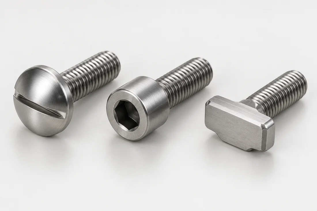
Define why the head needs to change
A special head may solve tool access, a captured pocket, a low clearance envelope or a particular bearing face. Identify that function on the assembly drawing. A head shape selected only for appearance can miss the surface or clearance that actually controls installation.
Dimension the head independently from the drive
Specify outer shape, height, under-head transition and bearing geometry as well as the recess. If the head is captured in a pocket, include the pocket and insertion path. If a combination drive is used, show the two interfaces and engagement depths instead of assuming their names define a compatible profile.
Review forming, machining and final appearance together
Head geometry can affect tooling and secondary work. Review corner forms, access for machining and any visible surface requirements with the proposed route. Approve the finished head against both the installation envelope and the matching tool; a correct outer silhouette does not establish drive performance.
From drawing to approved samples
Provide the drawing, material, finish and intended assembly. Identify the drawing revision, prototype quantity and expected repeat demand. Where the first part is based on an existing sample, separately confirm material and hidden features rather than inferring them from appearance.
The typical sampling lead time, including tooling, is approximately 10–15 days. The schedule is confirmed after drawing review and agreement on the sample specification; material availability, special treatment and inspection requirements can affect the confirmed date. Confirm when the agreed schedule starts in the quotation. Sample approval and repeat-production delivery are separate milestones.