
 ZUFEK
Identify the functional axis
Show which shank, shoulder or thread establishes the assembly reference. Dimension the eccentric feature relative to that reference rather than an arbitrary drawing edge. If the thread does not locate the part in service, explain which smooth feature actually does.
Define offset and angular orientation
Specify the amount of eccentricity and any required orientation to a slot, flat or drive. An offset without angular control may be acceptable for one adjuster and unsuitable for another. Include the intended adjustment positions and how they will be identified during assembly.
Describe the mating contact
Provide the follower, bore or surface moved by the eccentric feature. Show clearances and travel limits. The assembly determines whether a geometric change produces the desired adjustment; the screw drawing alone cannot establish the motion of every connected component.
Choose an inspection setup that follows function
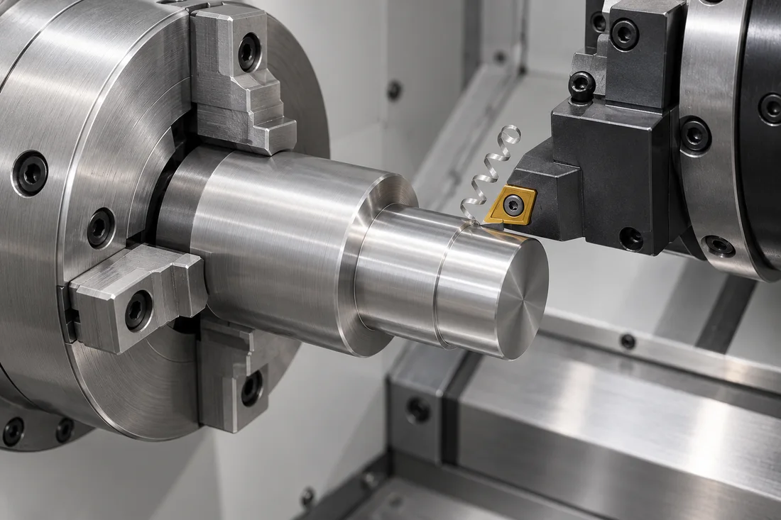
The inspection plan should establish the same reference features used in the design. Discuss the practical measurement of offset, form and orientation before production. A photograph can illustrate the concept but is not an adequate substitute for controlled datum and dimensional requirements.
Specification example
For a camera-module adjuster, show the feature that contacts the module and the surface that locates the screw. This helps distinguish the adjustment geometry from incidental machining surfaces.
RFQ checklist
- Functional locating axis
- Offset and orientation
- Mating contact and travel
- Critical datum relationships
- Agreed measurement setup
Use the RFQ preparation checklist, then submit your drawing for review. For acceptance requirements, see quality planning.
General guidance only. Material properties, tolerances, standards and manufacturing feasibility must be verified for the actual specification. This article does not establish a product performance guarantee.