

DONGGUAN ZUFEK PRECISION CO., LTD.
info@zufek.net
ROUTE 02 / BAR MACHINING

Swiss-Type & CNC Turning

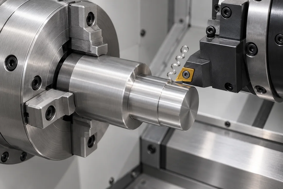
Bar-fed turning and turn-mill operations create drawing-specific steps, bores and other details with flexible programming.

CNC turning illustration with a supported bar and cutting insert at a shoulder
Swiss-Type & CNC Turning

Where it fits

Prototypes, varied geometries, small batches and parts with several machined features. Actual batch economics depend on cycle time, stock and setup.

Swiss-type and fixed-head choices

Part length-to-diameter ratio, support and the required operations guide the choice. Turn-mill capability can combine turning, flats, holes and tapped features where the machine setup permits.

Design inputs

Provide bore depth, wall thickness, datum relationships, burr limits and surface finish. Access, tool reach and workholding remain feasibility constraints.

Cost and properties

Material removal increases chip generation and may increase unit cost. A machined part is not universally weaker than a formed part: grade, geometry, heat treatment and loading determine performance.

Prepare a complete specification

Use the RFQ checklist, review materials and include the required inspection and documentation.
Drawing review example

Check the remaining wall before quoting a hollow screw

Illustrative drawing review. Confirm the route, dimensions and acceptance for your part.

What drives the route
Illustrative section only: an outside diameter of at least 7.96 mm and a bore of at most 4.04 mm leave 1.96 mm radial wall if concentric. With up to 0.15 mm centre offset at that section, the minimum wall is (7.96 − 4.04) ÷ 2 − 0.15 = 1.81 mm. This simple circular check excludes threads, cross-holes and local transitions.
What changes the quotation
Identify the minimum wall and bore axis where they matter, rather than only giving nominal diameters. A long bore, interrupted cut, tighter position requirement or second workholding setup can change cycle time, tool access and the inspection method.
How to release the sample
Check bore and outer geometry in the agreed datums and after release from the fixture. Separately verify hole intersections and burrs where a cable or fluid passes. The section calculation is a geometry check, not a pressure or load rating.

Related fastener families

Related technical guides

Continue through the process

Process decision and release matrix

Resolve these items during technical review. Each row identifies a decision or evidence requirement; it does not imply a universal process limit or an in-house equipment claim.

DecisionRequired inputRelease question
Setups and datumsIdentify locating faces, axes and relationships between stepsWhich features should share a setup to preserve the required relationship?
Bores and local featuresShow depth, diameter, intersections, flats and tool accessCan the feature be machined and checked with the proposed access?
Stock and final conditionSpecify grade/condition and later treatment or coatingWhich dimensions need allowance or acceptance after later processing?
Sample to productionIdentify route differences and repeated batch needsIs the approved prototype representative of the final production route?
AFTER PROCESSING

See the resulting feature.

Visual references help explain geometry and finish. Material properties, coating performance and acceptance require the agreed inspection methods.

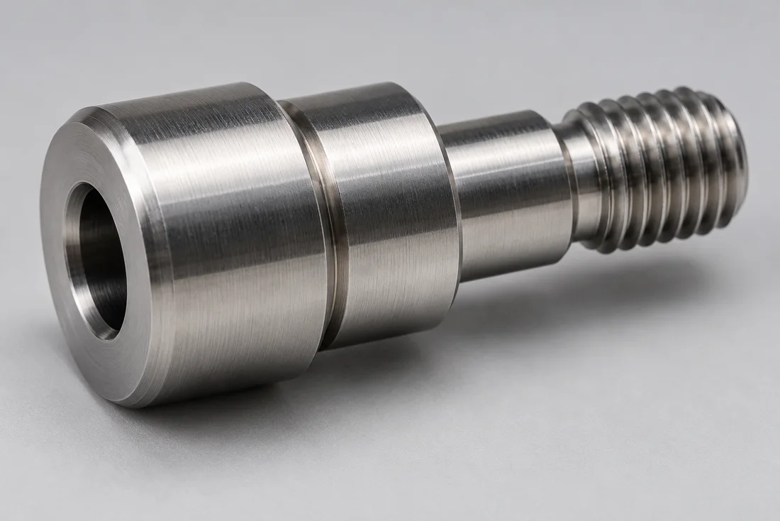
CNC turning — stepped geometry
Process outcome reference; final requirements follow the approved drawing.

Inputs and outputs for Swiss-Type & CNC Turning

The process review begins with Hollow & Through-Hole Screws, Eccentric & Angled Head Screws, Multi-Step & Multi-Shoulder Screws, Fine & Extra-Fine Pitch Screws and the actual drawing, not a generic equipment list. Identify the incoming stock or part condition and the dimensions that must remain controlled at this stage.

Use the process topics above to resolve where it fits; swiss-type and fixed-head choices; design inputs; cost and properties. Record the selected requirements in the order specification. A process name does not establish the resulting tolerance, property class or inspection coverage.

Coordinate the next operation

The next review may involve Secondary & Precision Operations or Thread Rolling, Cutting & Tapping. Check which surfaces are used to locate the part, whether the next operation changes dimensions and at what stage final acceptance is measured. Where a requirement cannot be checked after assembly or finishing, agree an intermediate check as well as final verification.

For samples involving tooling, the typical lead time is approximately 10–15 days, subject to drawing review and confirmation of material, finishing and inspection scope. The complete route determines the confirmed schedule; the duration is not a promise for each individual process.

CONNECTED SPECIFICATION TOPICS

Connect the part to its requirements.

Review these related topics for this design or route. Grade, treatment, geometry and acceptance remain drawing-specific.

START YOUR NEXT PROJECT

Discuss the route behind your drawing.

Share your drawing, quantity and application requirements with our team.

Request a quote
Get a quote ↗Email us

Choose how this website uses optional storage. You can change your choice at any time.

Your preferences are saved in this browser for 180 days. You can change or withdraw consent at any time. Withdrawal stops optional analytics and removes source information stored in your browser. Website access records are managed separately; contact us to exercise your privacy rights.

Read the cookie policy