

DONGGUAN ZUFEK PRECISION CO., LTD.
info@zufek.net
PROCESS / FUNCTIONAL FEATURES

Secondary & Precision Operations

Local holes, flats, grooves and finished diameters often create the functional difference in a non-standard fastener.

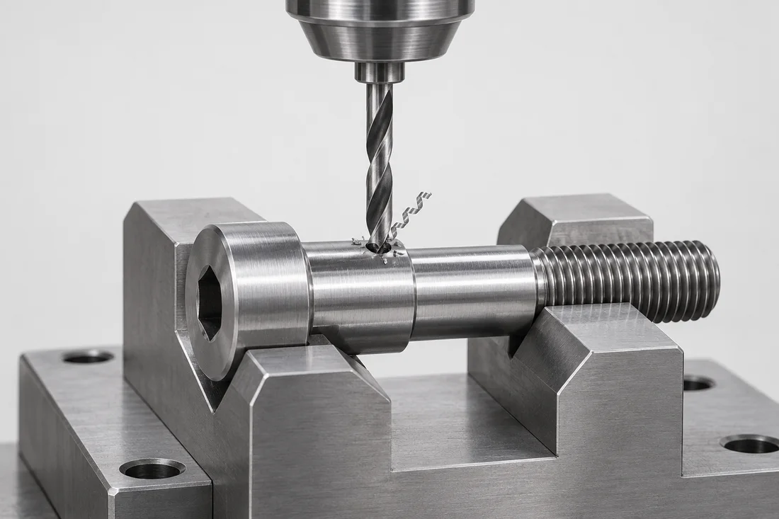
Radial drilling illustration with the shoulder screw supported in a V-block
Secondary & Precision Operations

Drilling, reaming and milling

Axial bores, radial holes, pin holes, flats, squares, drive recesses and local slots. Define position, edge breaks, hole exits and access.

Knurling, grooves and tip work

Straight or diamond knurls, circlip grooves, thread reliefs, oil grooves, tip cuts and controlled end shapes. Some features can be formed; others are machined.

Eccentric, angled and press operations

Offset turning, angled faces, undercuts, clinching and controlled crimping require an explicit setup and inspection plan.

Grinding and specialist routes

External, centerless or thread grinding may suit specific size, surface and form requirements. A g6 or h7 shaft tolerance does not mandate centerless grinding in every case. Wire EDM and laser operations are reviewed only where geometry and economics justify them.

Prepare a complete specification

Use the RFQ checklist, review materials and include the required inspection and documentation.
Drawing review example

Control the hidden edge of an intersecting hole

Illustrative drawing review. Confirm the route, dimensions and acceptance for your part.

What drives the route
A radial pin or feed hole can break into an axial bore. Dimension its position from the functional face or axis, and identify the inner intersection as a separate edge from the visible outer entrance. Specify allowed edge break and passage clearance together.
What changes the quotation
Show whether a deburring tool can reach the inner edge without enlarging the passage or scratching a sealing face. Workholding, access, a specialist deburring operation and a separate inspection setup can cost more than drilling the hole itself.
How to release the sample
Agree a method that actually sees or evaluates the hidden intersection, such as an accessible optical check or a sectioned first sample where appropriate. Define the production check separately. A clean outer entry and passing hole diameter do not establish internal burr acceptance.

Related fastener families

Related technical guides

Continue through the process

Process decision and release matrix

Resolve these items during technical review. Each row identifies a decision or evidence requirement; it does not imply a universal process limit or an in-house equipment claim.

DecisionRequired inputRelease question
Feature relationshipDefine hole, flat, slot or step from the functional datumsIs position/orientation specified separately from feature size?
Access and edgesShow hole exits, intersections and permitted edge breaksCan an internal burr be reached and checked?
Finishing operationState size, form and surface requirements in the final conditionIs grinding or a specialist operation justified by the requirement?
Process locationIdentify surfaces used for holding after earlier operationsCan the setup preserve the required geometry without damaging the part?
AFTER PROCESSING

See the resulting feature.

Visual references help explain geometry and finish. Material properties, coating performance and acceptance require the agreed inspection methods.

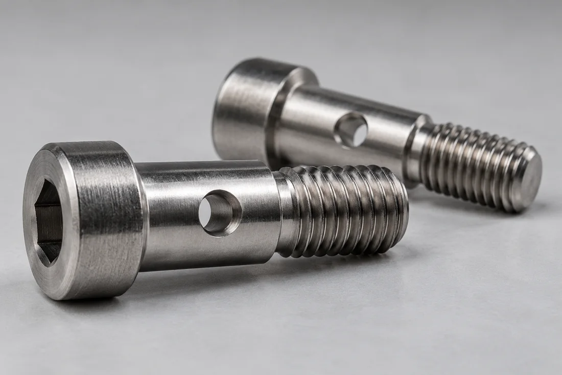
Secondary machining — cross hole
Process outcome reference; final requirements follow the approved drawing.

Inputs and outputs for Secondary & Precision Operations

The process review begins with Hollow & Through-Hole Screws, Knurled Thumb & Adjustment Screws, Eccentric & Angled Head Screws, Cross-Drilled & Head-Hole Screws and the actual drawing, not a generic equipment list. Identify the incoming stock or part condition and the dimensions that must remain controlled at this stage.

Use the process topics above to resolve drilling, reaming and milling; knurling, grooves and tip work; eccentric, angled and press operations; grinding and specialist routes. Record the selected requirements in the order specification. A process name does not establish the resulting tolerance, property class or inspection coverage.

Coordinate the next operation

The next review may involve Cleaning, Locking & Assembly or CCD Vision & Dimensional Inspection. Check which surfaces are used to locate the part, whether the next operation changes dimensions and at what stage final acceptance is measured. Where a requirement cannot be checked after assembly or finishing, agree an intermediate check as well as final verification.

For samples involving tooling, the typical lead time is approximately 10–15 days, subject to drawing review and confirmation of material, finishing and inspection scope. The complete route determines the confirmed schedule; the duration is not a promise for each individual process.

CONNECTED SPECIFICATION TOPICS

Connect the part to its requirements.

Review these related topics for this design or route. Grade, treatment, geometry and acceptance remain drawing-specific.

START YOUR NEXT PROJECT

Discuss the route behind your drawing.

Share your drawing, quantity and application requirements with our team.

Request a quote
Get a quote ↗Email us

Choose how this website uses optional storage. You can change your choice at any time.

Your preferences are saved in this browser for 180 days. You can change or withdraw consent at any time. Withdrawal stops optional analytics and removes source information stored in your browser. Website access records are managed separately; contact us to exercise your privacy rights.

Read the cookie policy