
 ZUFEK
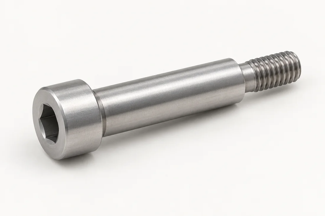
Turn the diameter limits into a review record
Worked review only. Inputs and acceptance criteria belong to the actual drawing; no customer test result or universal performance rating is claimed.
- Minimum diametral clearance
- 8.010 − 8.005 = 0.005 mm, using the smallest bore and largest shoulder.
- Maximum diametral clearance
- 8.030 − 7.995 = 0.035 mm, using the largest bore and smallest shoulder.
Define the shoulder
Dimension shoulder diameter and shoulder length independently from thread length. Explain whether the shoulder serves as a locating surface, bearing surface or spacer. The functional role helps identify which features need closer review.
Show how the thread ends
State thread designation and length, and show any relief or transition at the shoulder. Check how the screw seats in the mating assembly. Do not assume the end of the usable thread is identical to the end of the visible thread form.
Review head access and seating
Include head diameter, height and drive configuration. Consider the tool clearance and seating surface in the assembly. A head that fits the drawing may still be inaccessible once neighboring parts are installed.
Communicate functional tolerances
Mark the mating bore relationship and any surface finish requirement that affects motion or fit. Tolerances should be established by the application engineer and confirmed during manufacturing review.
Draw the assembly stack, not only the screw
Show the seating face, moving component, washer or bushing and intended axial clearance. Dimension the shoulder length against this stack. If the shoulder is too short, tightening can clamp the moving part; too long can leave excessive movement. Review the worst permitted stack before approving shoulder length, rather than adjusting it after a binding prototype is received.
Choose datums that match the locating function
Identify the axis and face that locate the part in service. Decide whether shoulder form, runout or another specified relationship affects the mechanism. Listing only outside diameters can leave the functional relationship undefined. Agree how the relationship is checked, particularly if the part is located differently during successive machining operations.
Approve the final supplied surface
Treatment and coating may change the condition used to accept the shoulder. State final limits and coating coverage on the functional surface. The inspection record should distinguish shoulder measurement from thread gauging. A correct thread does not establish that the pivot fits, and a correct external silhouette does not establish surface texture.
Worked review: calculate diametral clearance separately
Assume a finished shoulder diameter of 8.000 ± 0.005 mm and a mating bore of 8.020 ± 0.010 mm. Compare the smallest bore with the largest shoulder, then the largest bore with the smallest shoulder. The resulting 0.005–0.035 mm range is diametral clearance, not radial clearance or an axial gap. These illustrative inputs do not define a standard fit or an approved operating range. The designer still specifies the functional range, temperature basis, datum relationships and final surface condition.
Use the RFQ preparation checklist, then submit your drawing for review. For acceptance requirements, see quality planning.
General guidance only. Material properties, tolerances, standards and manufacturing feasibility must be verified for the actual specification. This article does not establish a product performance guarantee.