
 ZUFEK
Shoulder & Step Screws
A head, a locating shoulder and a threaded section combine fastening with controlled spacing or movement.
Discuss this custom part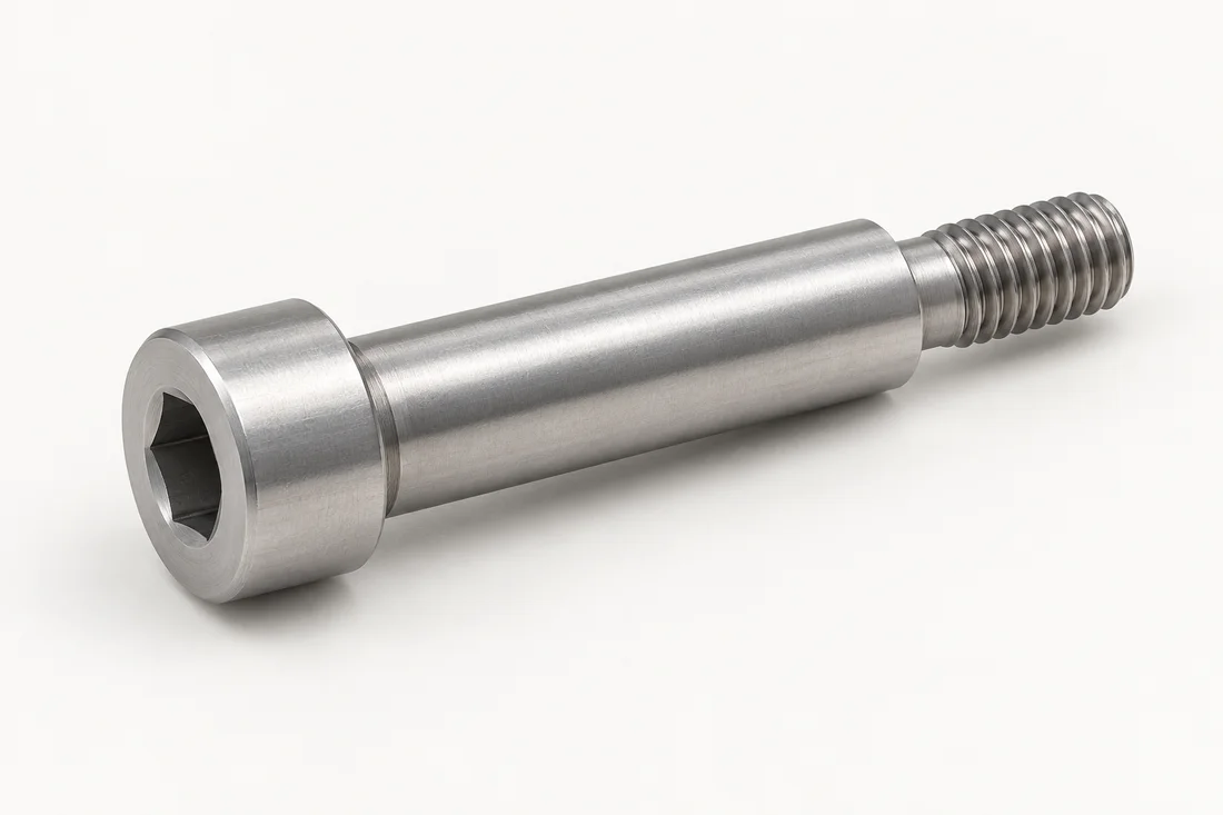
Check the bore fit separately from the axial clearance
The shoulder-to-bore interface guides movement; the distance between the seating faces controls the axial stack. Define both in the finished condition rather than treating a thread fit as the locating fit.
- Shoulder and mating bore: specify the two limits, the reference axis and any functional surface requirement.
- Seating and transition: show the mating chamfer or counterbore so the incomplete thread or relief does not prevent seating.
- After finishing: identify the surfaces affected by treatment or coating and the stage at which the final fit is checked.
Read the clearance calculation below alongside these interfaces. A satisfactory axial gap does not by itself establish the bore fit or the required geometric relationship.
Calculate the shoulder clearance from both tolerance limits
For a moving plate, shoulder length must be compared with the complete stack between the seating faces. Include the washer, bushing and plate in that stack; overall screw length does not determine movement clearance.
Assume a shoulder length L of 8.20 ± 0.03 mm and a complete moving stack S of 8.00 ± 0.05 mm. The illustrative required axial clearance is 0.10–0.30 mm. Both dimensions refer to the final supplied condition.
| Calculation | Result |
|---|---|
| Minimum clearance: shortest shoulder minus thickest stack | 8.17−8.05=0.12 mm |
| Maximum clearance: longest shoulder minus thinnest stack | 8.23−7.95=0.28 mm |
The calculated 0.12–0.28 mm interval lies inside the illustrative requirement. That answers this axial-clearance question only: separately check shoulder-to-bore fit, transition clearance, thread engagement and the effect of the actual assembly and service conditions.
Use the drawing checklist to record both interfacesTooling and sampling typically take approximately 10–15 days after technical review and confirmation. Confirm the starting milestone, sample acceptance and repeat-production schedule in the quotation.
Where this design fits
Automation, molds, fixtures, pivots and guided assemblies.
What to include in the RFQ
Include mating bore details, critical shoulder dimensions, surface texture and required dimensional inspection.
Open the complete RFQ checklist ↗Material and acceptance
Carbon steel, 10B21, SUS304/316, aluminum, copper/brass and titanium alloy requirements can be discussed. Suitability is specific to the part, grade and process.
Define material condition, coating, critical dimensions and required inspection records. A named product family does not imply a tested load, pressure or performance rating.
Make the features work together.
These routes are options for technical review. The approved drawing, quantity and material determine the actual sequence.
Related product designs
Application discussions
Useful technical reading
Shoulder screws: drawing and acceptance matrix
Use this matrix to prepare a review. Values and acceptance methods are agreed for the actual part; these are specification fields, not catalog limits.
| Interface | What to define | Verification discussion |
|---|---|---|
| Locating diameter | Diameter limits, mating bore and accepted final condition | Check size with a suitable calibrated method; assess form separately when specified |
| Axial shoulder length | Seating face to the shoulder transition; stack and required clearance | Measure from the functional face; check the assembled axial condition |
| Shoulder-to-thread relationship | Datum axis, transition clearance and usable thread | Agree geometry measurement and thread gauging separately |
| Bearing surface | Surface texture, treatment coverage and edge condition | Use the required surface method; a silhouette does not establish texture |
Common specification questions
Can the shoulder and thread have different diameters?
Yes, the shoulder and thread are specified independently. Review the transition, available mating clearance and effective thread engagement as one geometry.
Is every shoulder screw ground?
No. The final size, form and surface requirements determine the finishing route. Review the need for grinding with treatment distortion and the final acceptance condition.
Follow a complete application design
Explore a proposed assembly, the fastener choices, manufacturing review and sample validation plan. This is an illustrative design study, with no claimed customer delivery or measured performance.
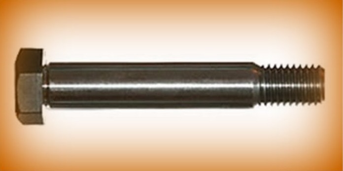
Review the fixture shoulder and axial-stack concept ↗Shoulder bolt reference photograph
Connect the part to its requirements.
Review these related topics for this design or route. Grade, treatment, geometry and acceptance remain drawing-specific.
Carbon & Alloy Steel ↗
Specify the finished fastener property class, not a strength inferred from the raw grade. Common nominal class references include 8.8, 10.9 and 12.9.
MATERIAL & FINAL CONDITION10B21 Boron Steel ↗
10B21 is a grade designation, not a finished strength class. There is no single tensile strength that applies to every 10B21 screw.
MATERIAL & FINAL CONDITIONSUS304 & SUS316 Stainless Steel ↗
A2/A4 groups and classes such as 70 or 80 describe finished stainless fasteners under the applicable specification. SUS304 or SUS316 alone does not establish A2-70 or A4-80 performance.
ENGINEERING GUIDEHow to prepare an inspection plan for custom screws ↗
Build an inspection plan one characteristic at a time. For each drawing requirement, record the acceptance condition, a suitable method, the inspection stage and coverage, and the evidence retained. The worked rows below show how to turn a shoulder-screw drawing into an inspection record.
ENGINEERING GUIDEHigh-strength screw coatings and hydrogen-risk review ↗
A high-strength steel fastener needs a coating decision that considers both corrosion and hydrogen exposure throughout processing.
How is a shoulder screw different from a fully threaded bolt?
A shoulder screw has an unthreaded bearing or locating section between its head and thread. Select that shoulder for the required rotation, location or spacing function, and specify thread engagement separately. A fully threaded bolt does not provide the same smooth bearing surface.
How do I choose the shoulder length without clamping a moving part?
Review the complete axial stack, including washers and the mating seat. The shoulder must seat as intended while preserving the specified movement clearance. Show the assembly and tolerance stack on the drawing; nominal shoulder length alone cannot establish the final clearance.
Send the details for your shoulder & step screws.
Share your drawing, quantity and application requirements with our team.