

DONGGUAN ZUFEK PRECISION CO., LTD.
info@zufek.net
COMPOUND STRUCTURES

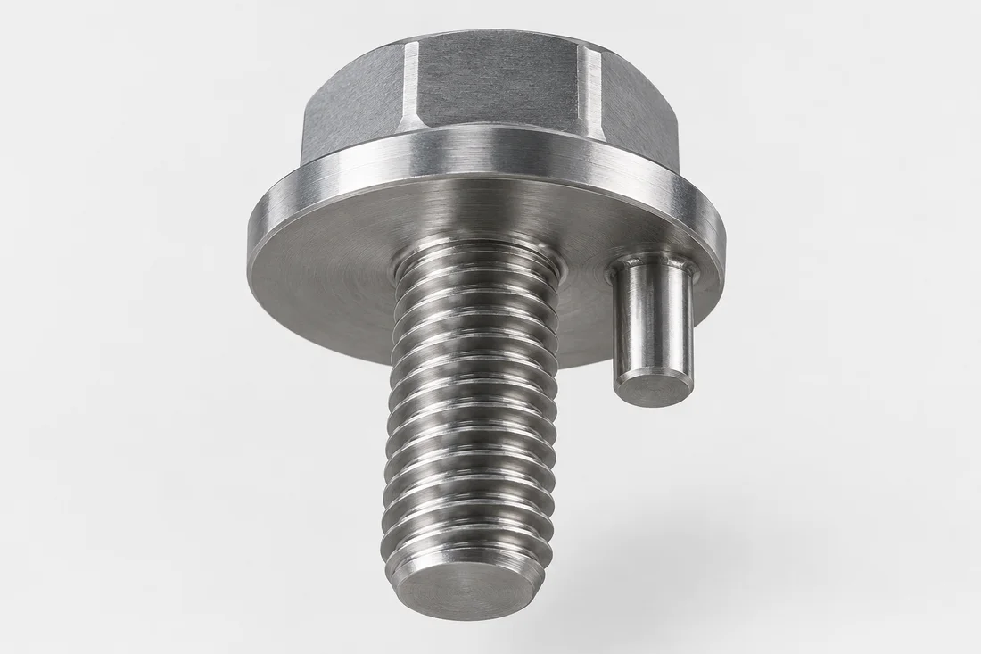
Screws with Integral Locating Pins

A local pin or locating extension combines a screw connection with a drawing-defined positioning feature.

Discuss this custom part
Custom screw illustration with an offset integral locating pin
Screws with Integral Locating Pins

Where this design fits

Locating fixtures and assemblies combining alignment with retention.

What to include in the RFQ

Provide the mating hole and assembly direction. Confirm which feature locates and which provides the clamp.

Open the complete RFQ checklist ↗

Material and acceptance

Carbon steel, 10B21, SUS304/316, aluminum, copper/brass and titanium alloy requirements can be discussed. Suitability is specific to the part, grade and process.

Define material condition, coating, critical dimensions and required inspection records. A named product family does not imply a tested load, pressure or performance rating.

RELEVANT PROCESS OPTIONS

Make the features work together.

These routes are options for technical review. The approved drawing, quantity and material determine the actual sequence.

Related product designs

Application discussions

Useful technical reading

Drawing and sample checks

  1. Reference pin position to the mounting datum
  2. Verify alignment and insertion with the locating hole.

Relationship of pin to thread and shoulder

Show pin diameter, projection and position relative to the locating datum, not only to the overall outline. Review the assembly path so the pin can engage before the screw reaches its seated condition. The locating function and thread retention need independent acceptance checks.

Review the route before fixing the quotation

For screws with integral locating pins, review Swiss-Type & CNC Turning, Secondary & Precision Operations, CCD Vision & Dimensional Inspection against the drawing and quantity. Identify which features can be produced in the initial shape and which require a separate setup. A change to a functional shoulder, bore, drive or thread can change the proposed route as well as the inspection effort.

The drawing review should resolve pin location; pin geometry; feature relationship. Keep material condition and finishing allowance attached to those requirements. Define the acceptance condition for critical features and approve any proposed dimensional change before comparing samples with the original assembly.

From drawing to approved samples

Provide the mating hole and assembly direction. Confirm which feature locates and which provides the clamp. Identify the drawing revision, prototype quantity and expected repeat demand. Where the first part is based on an existing sample, separately confirm material and hidden features rather than inferring them from appearance.

The typical sampling lead time, including tooling, is approximately 10–15 days. The schedule is confirmed after drawing review and agreement on the sample specification; material availability, special treatment and inspection requirements can affect the confirmed date. Confirm when the agreed schedule starts in the quotation. Sample approval and repeat-production delivery are separate milestones.

START YOUR NEXT PROJECT

Send the details for your screws with integral locating pins.

Share your drawing, quantity and application requirements with our team.

Request a quote
Get a quote ↗Email us

Choose how this website uses optional storage. You can change your choice at any time.

Your preferences are saved in this browser for 180 days. You can change or withdraw consent at any time. Withdrawal stops optional analytics and removes source information stored in your browser. Website access records are managed separately; contact us to exercise your privacy rights.

Read the cookie policy