
 ZUFEK
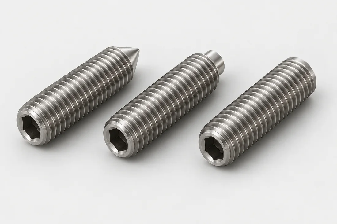
Choose the point around the mating surface
Cone, cup, flat and dog points serve different contact arrangements. A locating dog point needs its mating recess defined. A point that bites into a shaft may leave a mark that is unacceptable elsewhere. State whether the screw locates, clamps or acts as a stop, and show the surface it contacts before selecting the tip.
Keep engagement and access visible
A headless screw can sit below or project above the mating surface. Show the installed position, available tool depth and required thread engagement. A longer screw is not automatically a stronger connection if the actual engaged length is unchanged. Recess geometry, material condition and the mating tapped part all belong in the review.
Distinguish retention from fine adjustment
A set screw used as a shaft retainer has a different acceptance question from one used as a fine positioning stop. For a stop, define the contact end, adjustment travel and locking method. For retention, define the assembled functional requirement with the responsible designer; do not assign a universal holding force from the screw size alone.
Inspect the features that establish the function
Verify thread acceptance, tip form, overall length and the specified material condition. An external vision profile cannot by itself validate the socket or assembled holding behavior. Where a modified tip, side hole or eccentric feature is added, include its relationship to the thread axis and the agreed method for checking that relationship.
Review the route before fixing the quotation
For custom set screws & grub screws, review Swiss-Type & CNC Turning, Thread Rolling, Cutting & Tapping, Material-Specific Heat Treatment against the drawing and quantity. Identify which features can be produced in the initial shape and which require a separate setup. A change to a functional shoulder, bore, drive or thread can change the proposed route as well as the inspection effort.
The drawing review should resolve tip options; thread options; additional features. Keep material condition and finishing allowance attached to those requirements. Define the acceptance condition for critical features and approve any proposed dimensional change before comparing samples with the original assembly.
From drawing to approved samples
State tip geometry, mating surface, drive and expected function. Clamping performance depends on the full assembly. Identify the drawing revision, prototype quantity and expected repeat demand. Where the first part is based on an existing sample, separately confirm material and hidden features rather than inferring them from appearance.
The typical sampling lead time, including tooling, is approximately 10–15 days. The schedule is confirmed after drawing review and agreement on the sample specification; material availability, special treatment and inspection requirements can affect the confirmed date. Confirm when the agreed schedule starts in the quotation. Sample approval and repeat-production delivery are separate milestones.