

DONGGUAN ZUFEK PRECISION CO., LTD.
info@zufek.net
PROCESS / THREAD GENERATION

Thread Rolling, Cutting & Tapping

The thread profile, material and batch conditions determine whether rolling, cutting, grinding or an internal tapping process is appropriate.

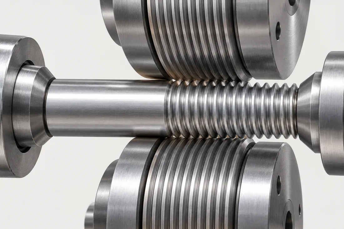
External thread rolling illustration with the workpiece supported between grooved dies
Thread Rolling, Cutting & Tapping

Flat-die and cylindrical-die rolling

External threads are formed by displacement. Suitable material condition, blank diameter and tool geometry are essential. Machine capability sets the actual size range; no universal M0.8–M12 limit applies.

Single-point cutting and special profiles

Turning can address specified pitches, tapers and special profiles where tooling and access permit. NPT, MJ and other named threads require the applicable complete specification, not an approximate profile.

Internal cut and form tapping

Cut tapping removes material; form tapping displaces a sufficiently ductile material and needs the correct pre-hole. Neither method is universally stronger in every grade and geometry.

Acceptance and sequence

Define designation, class, usable length, runout and gauging. Rolling may improve fatigue behavior in suitable conditions, but is not a blanket strength guarantee. Review whether threading occurs before or after heat treatment.

Prepare a complete specification

Use the RFQ checklist, review materials and include the required inspection and documentation.
Drawing review example

A gauge pass does not establish usable engagement

Illustrative drawing review. Confirm the route, dimensions and acceptance for your part.

What drives the route
For a short fine-pitch thread next to a locating shoulder, distinguish the usable full-form length from the lead-in and incomplete runout. Show the mating hole depth and entry chamfer so the shoulder can seat before the screw bottoms or encounters incomplete threads.
What changes the quotation
Supply the complete profile, pitch, class, direction and final condition. For rolling, review blank size, ductility and die runout; for cutting, review tool clearance and cycle time. Include the required coating allowance and any special gauge before comparing prices.
How to release the sample
Apply the agreed thread gauge in the final condition, then check usable length and runout separately. Trial the approved mating assembly where seating matters. A ring-gauge result alone cannot prove the available engagement or that the joint seats.

Related fastener families

Related technical guides

Continue through the process

Process decision and release matrix

Resolve these items during technical review. Each row identifies a decision or evidence requirement; it does not imply a universal process limit or an in-house equipment claim.

DecisionRequired inputRelease question
Thread definitionSpecify profile, diameter, pitch, handedness, class and usable lengthDoes the callout fully identify the mating interface?
Method selectionReview rolling/forming, cutting or tapping for the geometry and materialWhich method meets the actual profile and final requirements?
Transitions and endsShow relief, lead-in, blind ends and adjacent shouldersCan the mating part seat and obtain the required engagement?
Final acceptanceAgree gauges, custom-profile methods and coating allowanceIs acceptance defined in the supplied condition rather than only before finishing?
AFTER PROCESSING

See the resulting feature.

Visual references help explain geometry and finish. Material properties, coating performance and acceptance require the agreed inspection methods.

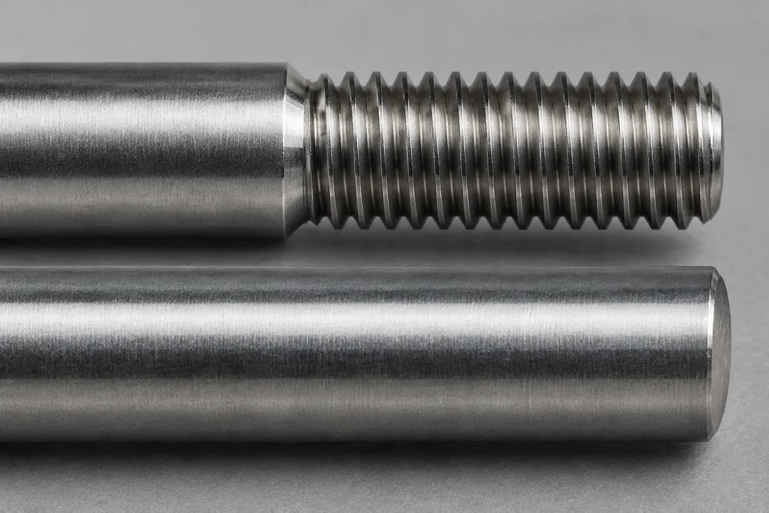
Threading — finished thread
Process outcome reference; final requirements follow the approved drawing.

Inputs and outputs for Thread Rolling, Cutting & Tapping

The process review begins with Fine & Extra-Fine Pitch Screws, Special & Compound Thread Profiles, Custom Double-Ended Studs, Custom Set Screws & Grub Screws and the actual drawing, not a generic equipment list. Identify the incoming stock or part condition and the dimensions that must remain controlled at this stage.

Use the process topics above to resolve flat-die and cylindrical-die rolling; single-point cutting and special profiles; internal cut and form tapping; acceptance and sequence. Record the selected requirements in the order specification. A process name does not establish the resulting tolerance, property class or inspection coverage.

Coordinate the next operation

The next review may involve Material-Specific Heat Treatment or CCD Vision & Dimensional Inspection. Check which surfaces are used to locate the part, whether the next operation changes dimensions and at what stage final acceptance is measured. Where a requirement cannot be checked after assembly or finishing, agree an intermediate check as well as final verification.

For samples involving tooling, the typical lead time is approximately 10–15 days, subject to drawing review and confirmation of material, finishing and inspection scope. The complete route determines the confirmed schedule; the duration is not a promise for each individual process.

CONNECTED SPECIFICATION TOPICS

Connect the part to its requirements.

Review these related topics for this design or route. Grade, treatment, geometry and acceptance remain drawing-specific.

START YOUR NEXT PROJECT

Discuss the route behind your drawing.

Share your drawing, quantity and application requirements with our team.

Request a quote
Get a quote ↗Email us

Choose how this website uses optional storage. You can change your choice at any time.

Your preferences are saved in this browser for 180 days. You can change or withdraw consent at any time. Withdrawal stops optional analytics and removes source information stored in your browser. Website access records are managed separately; contact us to exercise your privacy rights.

Read the cookie policy