
 ZUFEK
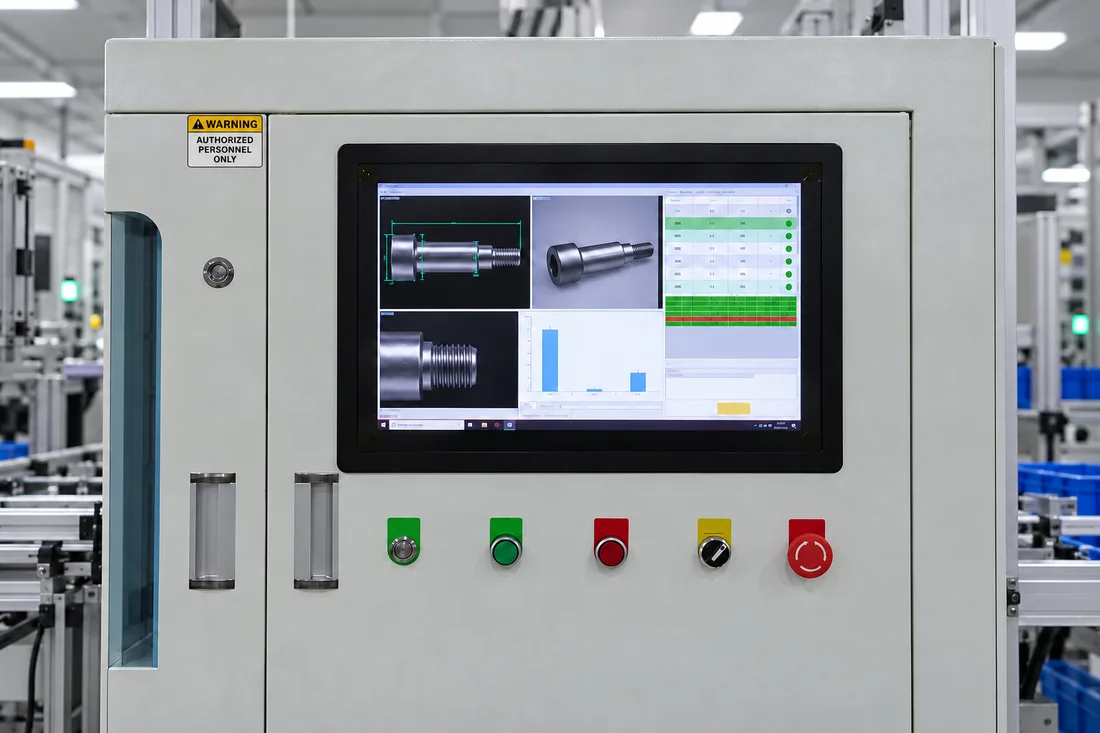
Choose the visible features to measure
Overall length, head diameter and stepped external profiles can be useful targets for optical checks when they are presented clearly. Identify the actual drawing characteristics rather than requesting a generic camera inspection with no defined measurements or acceptance limits.
Review presentation and lighting
Stable support, suitable optics and controlled lighting help produce consistent edges. Backlighting is useful for silhouette-based checks, while other surface features may require a different lighting arrangement. Establish the inspection view for the part rather than assuming one image reveals every characteristic.
Recognize what the image does not establish
A visible outline does not prove material grade, hardness or internal features hidden from the camera. Thread functional acceptance may require the specified gauges or other methods. The inspection plan should identify complementary checks instead of presenting one camera station as complete evidence of every requirement.
Validate and maintain the inspection program
Agree the measurement setup, acceptance limits, reference parts and any checks used to confirm consistent operation. Document changes to part revision or finish that may affect the image. Inspection coverage and handling of rejected parts should be defined for the actual order.
Validate presentation and edge visibility
Review part orientation, lighting, contrast and focus for each intended characteristic. Compare the programmed result with a suitable reference measurement using representative parts. Do not transfer a setup unchanged to a different coating, shape or presentation without checking whether the relevant edge is still detected appropriately.
Define coverage and reject handling
Document which external features the system evaluates and which are outside the validated program. Agree how borderline and rejected parts are handled, how setup changes are controlled and what record is retained. A pass indication is evidence only for the characteristics and conditions actually evaluated, not for every requirement on the drawing.
Pair optical checks with the missing methods
Use appropriate complementary checks for internal passages, thread acceptance, surface texture and material properties. A silhouette may show part of a thread outline without establishing the complete thread fit. Mitutoyo’s vision-measurement guide describes optical edge detection and alignment; the production inspection plan must still establish applicability to the actual screw.
Specification example
For a shoulder screw, define head diameter, shoulder length and overall length as separate checks. Then specify how the thread and any internal drive requirements are verified outside that silhouette measurement.
RFQ checklist
- Drawing characteristics and limits
- Required views and presentation
- Calibration and reference checks
- Complementary gauges or tests
- Coverage and reject-handling plan
Use the RFQ preparation checklist, then submit your drawing for review. For acceptance requirements, see quality planning.
General guidance only. Material properties, tolerances, standards and manufacturing feasibility must be verified for the actual specification. This article does not establish a product performance guarantee.