

DONGGUAN ZUFEK PRECISION CO., LTD.
info@zufek.net
ROUTE 03 / HEATED FORMING

Hot Heading & Forging

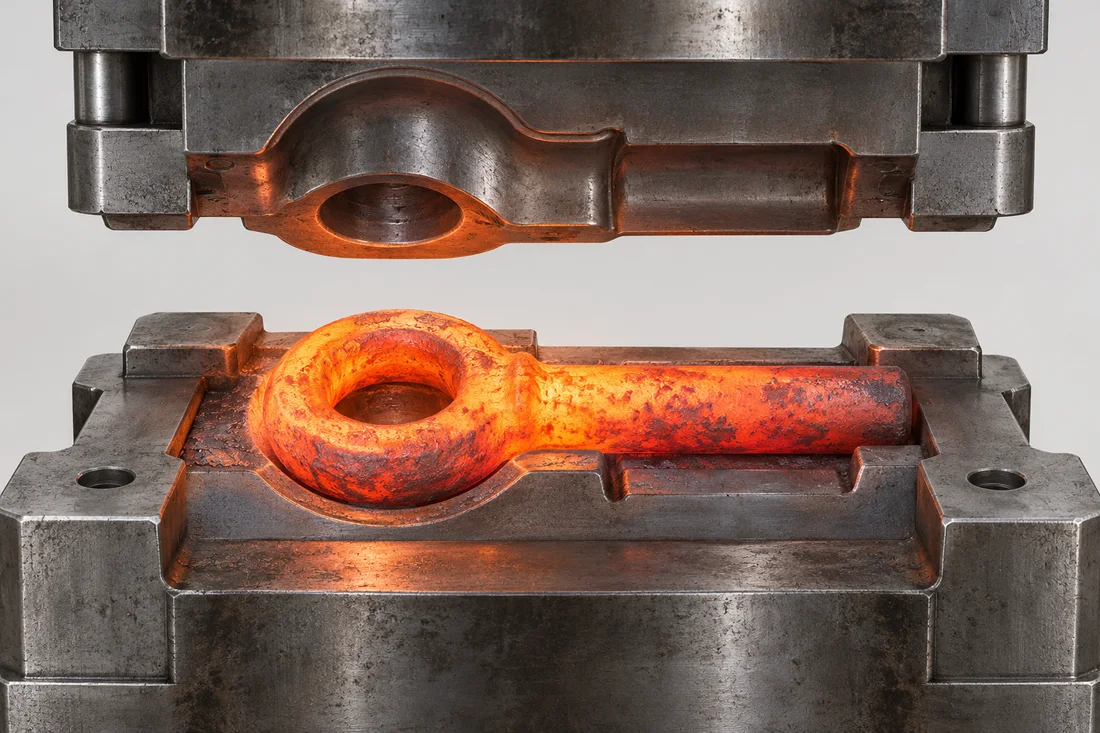
Heated stock can be formed into larger or heavier geometries before finishing operations define the final interfaces.

Hot forging process illustration with a heated eye-shaped blank and aligned dies
Hot Heading & Forging

Where it fits

Large heads, eye forms and substantial sections may suit hot forging. There is no universal M24 changeover; material, equipment and shape determine the practical route.

Typical follow-up work

Trimming, scale removal, machining of seating faces or holes, threading and the specified heat treatment.

Load-bearing features

Radii, section transitions and material condition must be considered with the intended load. Lifting-related designs need an approved specification and appropriate verification.

Quotation inputs

Include stock grade, geometry, quantity, mechanical requirements and the scope of any required testing and documentation.

Prepare a complete specification

Use the RFQ checklist, review materials and include the required inspection and documentation.
Drawing review example

Separate the forged eye blank from the finished load path

Illustrative drawing review. Confirm the route, dimensions and acceptance for your part.

What drives the route
For a large eye component, draw the eye, pin or hook contact, shank transition and final seating face. Review the proposed parting line, trimming and machining stock so the finished bearing surfaces are not confused with the as-forged outline.
What changes the quotation
Quote the heated blank, tooling, trimming or scale removal and later machining as a complete route. Define any treatment, mechanical verification and document scope at quotation; a large eye shape does not by itself establish suitability for lifting.
How to release the sample
Confirm finished bore and seat geometry, material and treatment traceability and the agreed mechanical verification. If the part is intended for lifting, the applicable design, load direction, marking and qualification must be approved for that use before release.

Related fastener families

Related technical guides

Continue through the process

Process decision and release matrix

Resolve these items during technical review. Each row identifies a decision or evidence requirement; it does not imply a universal process limit or an in-house equipment claim.

DecisionRequired inputRelease question
Preform and stockDefine grade, major section changes and final shapeWhat material and forging plan is proposed for the actual geometry?
Machining allowanceIdentify flash/scale removal and finished datumsWhich interfaces are accepted only after subsequent machining?
Material conditionSpecify heat treatment and mechanical acceptanceWhat evidence establishes the required finished properties?
Load-related applicationSupply the approved design and traceable verification scopeIf lifting is involved, who approves the design and applicable rating?
AFTER PROCESSING

See the resulting feature.

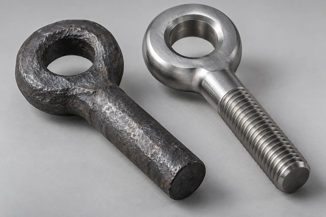
Visual references help explain geometry and finish. Material properties, coating performance and acceptance require the agreed inspection methods.

Hot forging — forged blank
Process outcome reference; final requirements follow the approved drawing.

Inputs and outputs for Hot Heading & Forging

The process review begins with Custom Eye & Articulating Bolts, Custom Lifting Eye Bolt Designs, Custom Square Head Bolts and the actual drawing, not a generic equipment list. Identify the incoming stock or part condition and the dimensions that must remain controlled at this stage.

Use the process topics above to resolve where it fits; typical follow-up work; load-bearing features; quotation inputs. Record the selected requirements in the order specification. A process name does not establish the resulting tolerance, property class or inspection coverage.

Coordinate the next operation

The next review may involve Material-Specific Heat Treatment or Thread Rolling, Cutting & Tapping. Check which surfaces are used to locate the part, whether the next operation changes dimensions and at what stage final acceptance is measured. Where a requirement cannot be checked after assembly or finishing, agree an intermediate check as well as final verification.

For samples involving tooling, the typical lead time is approximately 10–15 days, subject to drawing review and confirmation of material, finishing and inspection scope. The complete route determines the confirmed schedule; the duration is not a promise for each individual process.

CONNECTED SPECIFICATION TOPICS

Connect the part to its requirements.

Review these related topics for this design or route. Grade, treatment, geometry and acceptance remain drawing-specific.

START YOUR NEXT PROJECT

Discuss the route behind your drawing.

Share your drawing, quantity and application requirements with our team.

Request a quote
Get a quote ↗Email us

Choose how this website uses optional storage. You can change your choice at any time.

Your preferences are saved in this browser for 180 days. You can change or withdraw consent at any time. Withdrawal stops optional analytics and removes source information stored in your browser. Website access records are managed separately; contact us to exercise your privacy rights.

Read the cookie policy