

DONGGUAN ZUFEK PRECISION CO., LTD.
info@zufek.net
ROUTE 01 / FORMING

Multi-Station Cold Heading

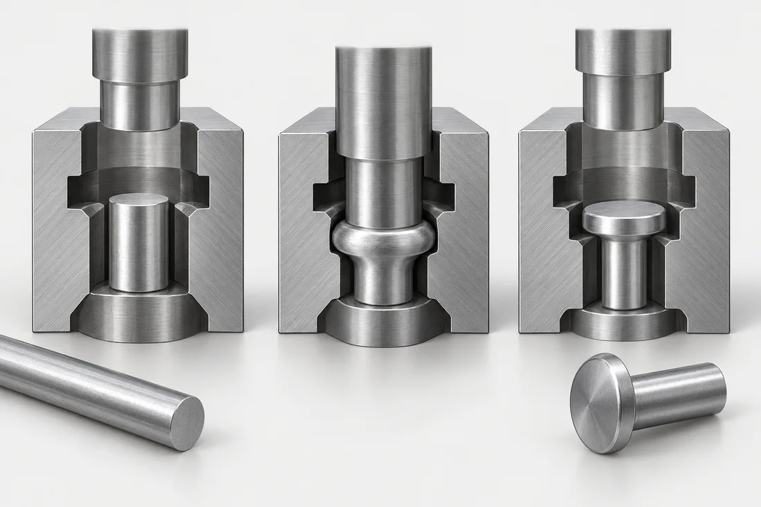
Wire is cut and formed through a sequence of dies. Head, flange and some shoulder features can be integrated into a repeatable production route.

Cold heading process illustration with cut blank, forming punch, die and headed blank
Multi-Station Cold Heading

Where it fits

Repeated screw geometries and production volumes that justify dedicated tooling. Head volume, material formability and extrusion limits guide the die sequence.

Operations to review

Cut-off, preforming, heading, extrusion, local reduction and pre-piercing. Deep bores, side features and complex undercuts may require later machining.

What drives the quotation

Tooling investment, batch quantity, material, head-to-shank ratios and the secondary operations that remain. Cold heading is not automatically the cheapest route at every volume.

Mechanical considerations

Cold forming can provide favorable grain flow and work hardening. Final properties still depend on material, deformation, heat treatment and verified acceptance requirements.

Prepare a complete specification

Use the RFQ checklist, review materials and include the required inspection and documentation.
Drawing review example

Cold heading a flanged screw with a deep drive

Illustrative drawing review. Confirm the route, dimensions and acceptance for your part.

What drives the route
Review the head and recess together in section. Enlarging the flange changes the metal volume to be moved, while a deeper drive leaves less material below the recess. Identify the under-head transition and usable bearing face before splitting the blank into forming stages.
What changes the quotation
Separate the cost of heading tools from recurring pieces and any later recess, shoulder or hole machining. Ask which revision changes would require a tool change and whether the proposed wire condition and batch size support the formed route.
How to release the sample
Use samples from the intended forming route. Confirm the recess fit, flange seating and under-head geometry on the finished part, and agree what forming defects are unacceptable and how they will be checked. A turned mock-up can prove assembly access without proving formed-head quality.

Related fastener families

Related technical guides

Continue through the process

Process decision and release matrix

Resolve these items during technical review. Each row identifies a decision or evidence requirement; it does not imply a universal process limit or an in-house equipment claim.

DecisionRequired inputRelease question
Geometry and toolingIdentify head volume, steps, recess, blank and any later machiningWhat can be formed and which features still need a separate operation?
Material and wire conditionSpecify grade and requirements for the intended final partIs the proposed input suitable for the forming and treatment route?
Production economicsSeparate tooling, samples, recurring quantity and secondary workDoes the complete route make sense at the expected repeat volume?
Sample releaseIdentify production-route samples and critical formed featuresWhat must be reconfirmed if an early prototype was machined?
AFTER PROCESSING

See the resulting feature.

Visual references help explain geometry and finish. Material properties, coating performance and acceptance require the agreed inspection methods.

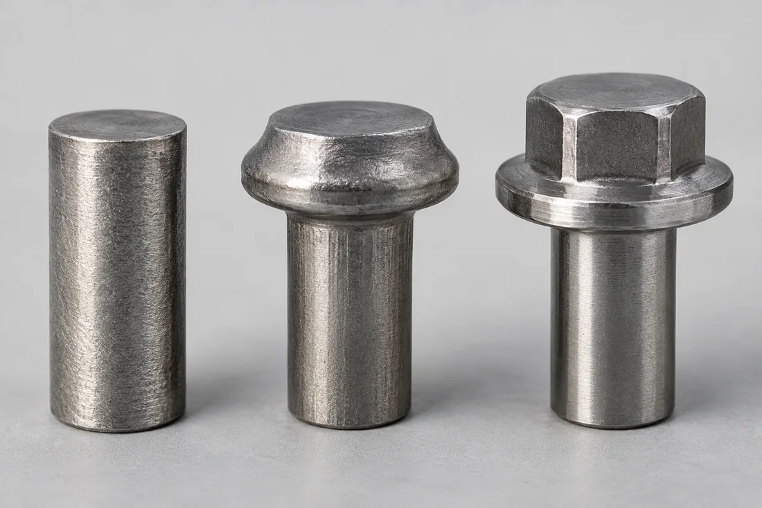
Cold heading — formed blank
Process outcome reference; final requirements follow the approved drawing.

Inputs and outputs for Multi-Station Cold Heading

The process review begins with Shoulder & Step Screws, Custom Flange Screws, Security & Tamper-Resistant Screws, Custom Carriage Bolts and the actual drawing, not a generic equipment list. Identify the incoming stock or part condition and the dimensions that must remain controlled at this stage.

Use the process topics above to resolve where it fits; operations to review; what drives the quotation; mechanical considerations. Record the selected requirements in the order specification. A process name does not establish the resulting tolerance, property class or inspection coverage.

Coordinate the next operation

The next review may involve Cold Heading + Secondary Machining or Thread Rolling, Cutting & Tapping. Check which surfaces are used to locate the part, whether the next operation changes dimensions and at what stage final acceptance is measured. Where a requirement cannot be checked after assembly or finishing, agree an intermediate check as well as final verification.

For samples involving tooling, the typical lead time is approximately 10–15 days, subject to drawing review and confirmation of material, finishing and inspection scope. The complete route determines the confirmed schedule; the duration is not a promise for each individual process.

CONNECTED SPECIFICATION TOPICS

Connect the part to its requirements.

Review these related topics for this design or route. Grade, treatment, geometry and acceptance remain drawing-specific.

START YOUR NEXT PROJECT

Discuss the route behind your drawing.

Share your drawing, quantity and application requirements with our team.

Request a quote
Get a quote ↗Email us

Choose how this website uses optional storage. You can change your choice at any time.

Your preferences are saved in this browser for 180 days. You can change or withdraw consent at any time. Withdrawal stops optional analytics and removes source information stored in your browser. Website access records are managed separately; contact us to exercise your privacy rights.

Read the cookie policy