

DONGGUAN ZUFEK PRECISION CO., LTD.
info@zufek.net
CORE CUSTOM SCREWS

Custom Flange Screws

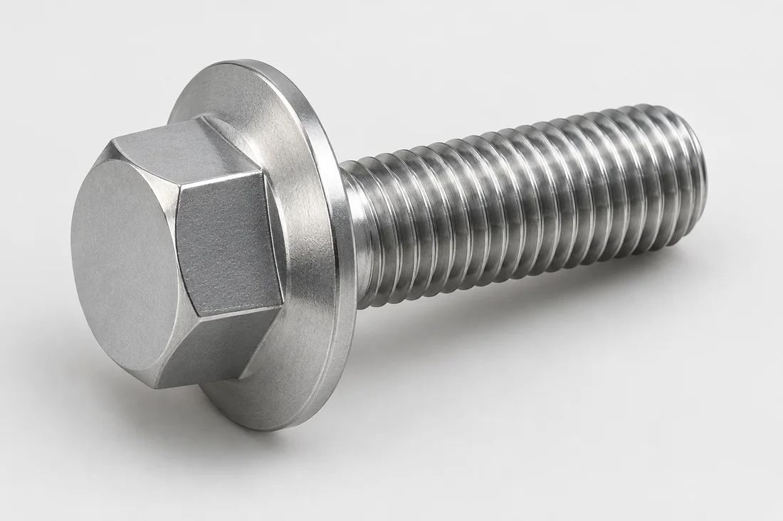
An integral flange provides a drawing-defined bearing footprint without a separately handled washer.

Discuss this custom part
Hex flange screw illustration with an integral bearing flange
Custom Flange Screws

Where this design fits

Equipment covers, brackets and assemblies requiring a controlled bearing area.

What to include in the RFQ

Include the mating material and bearing-face requirements. A larger flange does not automatically prevent surface damage.

Open the complete RFQ checklist ↗

Material and acceptance

Carbon steel, 10B21, SUS304/316, aluminum, copper/brass and titanium alloy requirements can be discussed. Suitability is specific to the part, grade and process.

Define material condition, coating, critical dimensions and required inspection records. A named product family does not imply a tested load, pressure or performance rating.

RELEVANT PROCESS OPTIONS

Make the features work together.

These routes are options for technical review. The approved drawing, quantity and material determine the actual sequence.

Related product designs

Application discussions

Useful technical reading

Flange screws: bearing and fit matrix

Use this matrix to prepare a review. Values and acceptance methods are agreed for the actual part; these are specification fields, not catalog limits.

InterfaceWhat to defineVerification discussion
Flange envelopeDiameter, thickness, corner and under-head transitionCheck clearance and the finished dimensional envelope
Bearing surfacePlain or defined serration, seating and permitted markingEvaluate contact on the mating material under the agreed assembly process
Thread engagementUsable thread and tapped-hole depthConfirm seating before bottoming and the agreed thread acceptance
Surface systemCoating specification, coverage and any friction requirementAgree coating and assembly evidence independently of dimension checks

Common specification questions

Will a wider flange prevent damage to a cover?

Not necessarily. Contact geometry, cover material, coating and tightening conditions determine the result. Review the actual interface.

Is an integral flange always equivalent to a washer?

No. Compare the bearing geometry, joint function and installation conditions before replacing a washer with an integral flange.

Follow a complete application design

Explore a proposed assembly, the fastener choices, manufacturing review and sample validation plan. This is an illustrative design study, with no claimed customer delivery or measured performance.

Review flange seating in an automotive enclosure concept ↗

Compare the bearing interface before enlarging the flange

A larger flange changes the contact envelope, but the clamped component still determines whether that contact is useful. Compare the face, coating and available seating area together.

123
Interface sketch — not to scale. Dimensions and acceptance follow the approved assembly drawing.
  1. Smooth integral flange: define the usable bearing face, adjacent radii and clearance to the mating recess.
  2. Serrated integral flange: review intended tooth contact, permissible marking and the effect on the mating coating.
  3. Separate washer: include washer dimensions, hardness or other required condition and its contribution to the axial stack.

Record which faces may contact and which must remain clear. Where marking, preload or repeated service matters, agree an assembly trial for the actual surface system instead of inferring performance from flange diameter.

Treat the flange as a bearing interface

Flange diameter changes the contact footprint, while flange thickness and under-head geometry affect the way the part seats. Supply the mating surface and available clearance. A wide flange is not automatically a substitute for a washer in every joint; compare the actual bearing surface, assembly arrangement and drawing requirements.

Distinguish plain and serrated bearing faces

A serrated face intentionally interacts with the mating surface and may affect appearance or coating. A plain flange has a different contact requirement. Identify whether the surface is soft, painted or otherwise sensitive, and define any permitted marking. Avoid specifying a texture only by a product photograph when its geometry affects the application.

Check finishing allowance and thread engagement

Coating applies to a three-dimensional part, including the bearing face and thread. Review the ordered finish with the thread fit and seating requirements. Where the joint has a shallow tapped hole, compare usable engagement and the under-head stack so the screw does not bottom before clamping. Head diameter alone cannot establish that the joint will assemble correctly.

Link sample approval to the mating part

For an equipment cover, review flange clearance, head access, seating and the agreed visual condition on representative parts. Define flange diameter, thickness and any flatness requirement independently. Choose mechanical and coating checks according to the specification; a dimensional screen of the flange does not establish clamp load or corrosion performance.

Review the route before fixing the quotation

For custom flange screws, review Multi-Station Cold Heading, Cold Heading + Secondary Machining, Coatings & Surface Treatments against the drawing and quantity. Identify which features can be produced in the initial shape and which require a separate setup. A change to a functional shoulder, bore, drive or thread can change the proposed route as well as the inspection effort.

The drawing review should resolve flange dimensions; bearing face; thin or enlarged flange. Keep material condition and finishing allowance attached to those requirements. Define the acceptance condition for critical features and approve any proposed dimensional change before comparing samples with the original assembly.

From drawing to approved samples

Include the mating material and bearing-face requirements. A larger flange does not automatically prevent surface damage. Identify the drawing revision, prototype quantity and expected repeat demand. Where the first part is based on an existing sample, separately confirm material and hidden features rather than inferring them from appearance.

The typical sampling lead time, including tooling, is approximately 10–15 days. The schedule is confirmed after drawing review and agreement on the sample specification; material availability, special treatment and inspection requirements can affect the confirmed date. Confirm when the agreed schedule starts in the quotation. Sample approval and repeat-production delivery are separate milestones.

CONNECTED SPECIFICATION TOPICS

Connect the part to its requirements.

Review these related topics for this design or route. Grade, treatment, geometry and acceptance remain drawing-specific.

START YOUR NEXT PROJECT

Send the details for your custom flange screws.

Share your drawing, quantity and application requirements with our team.

Request a quote
Get a quote ↗Email us

Choose how this website uses optional storage. You can change your choice at any time.

Your preferences are saved in this browser for 180 days. You can change or withdraw consent at any time. Withdrawal stops optional analytics and removes source information stored in your browser. Website access records are managed separately; contact us to exercise your privacy rights.

Read the cookie policy