
 ZUFEK
Project brief and system boundary
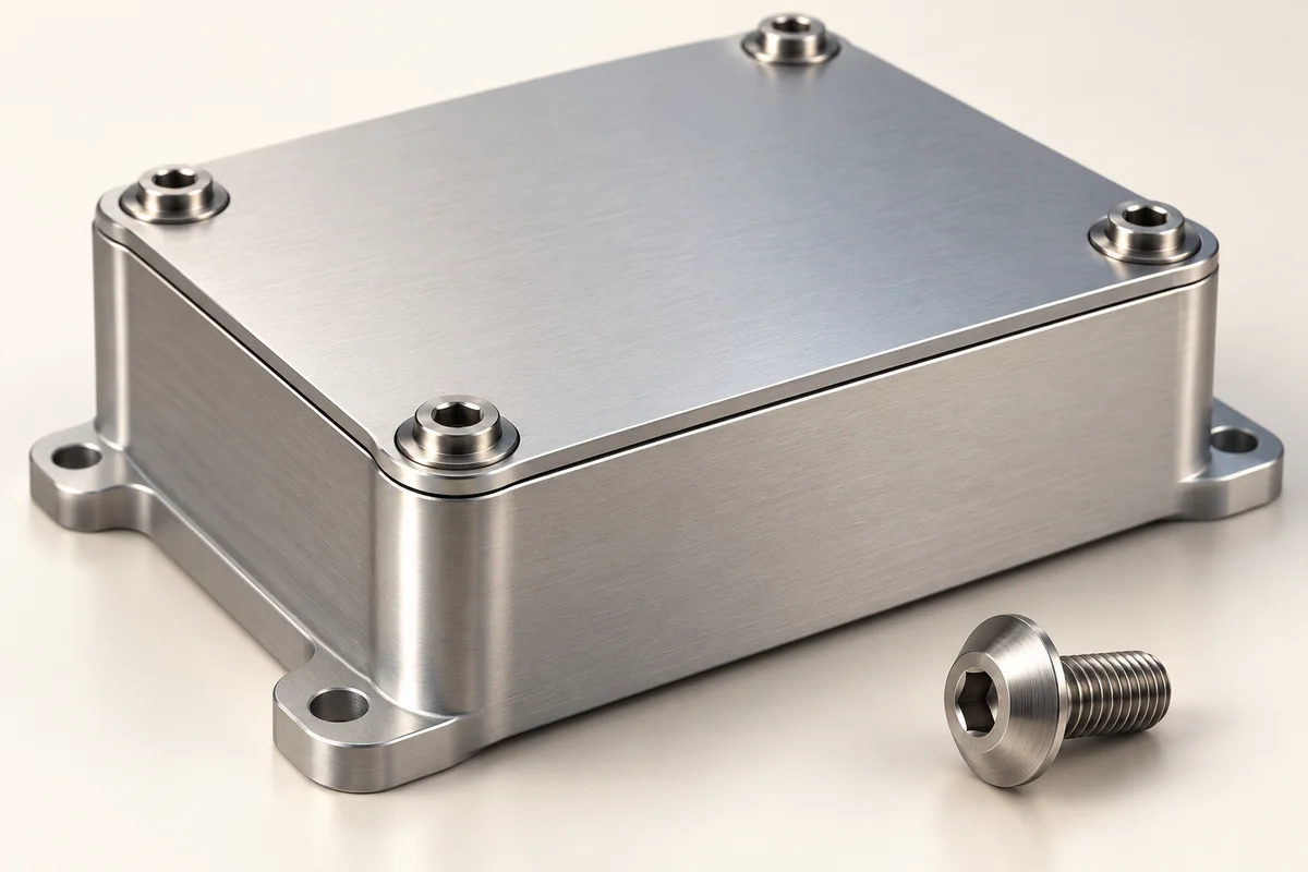
Design a custom screw concept for a serviceable automotive electronic-module cover fixed to a threaded housing. The proposed role is cover retention and controlled seating. The fastener is not assigned a crash, battery containment, electrical bonding or pressure-sealing function in this study. Any such requirement would change the design and approval scope. The study is a proposed engineering workflow, not an account of a delivered Mercedes-Benz, BMW or other customer project.
Assembly assumptions to confirm
Assume a cover with defined clearance holes, a housing with tapped bosses and restricted space around the screw head. The actual cover material, housing alloy, boss depth, gasket arrangement, external exposure and service access remain inputs to be confirmed. No screw diameter, tightening torque or strength class is released from these assumptions. Obtain a section through the joint and the cover stack before choosing dimensions.
Choose the fastener structure
Investigate an integral flange screw to reduce separately handled hardware and provide a defined bearing footprint. Compare the flange diameter and under-head radius with the cover hole, boss and nearby walls. Begin with a plain bearing face if appearance or cover marking is a concern; a serrated face requires a separate contact review. A special drive is an option only if restricted service access is a requirement. Confirm that the authorized tool can reach and fully engage the recess.
Resolve engagement and bottoming
Dimension the under-head stack and usable thread against the tapped boss. Verify that the screw seats on the intended bearing surface before the tip reaches the bottom of a blind hole. Define usable thread, lead-in and any unthreaded transition separately. If a gasket is present, its compression and the joint clamp requirement belong to the enclosure design; this study does not claim that a flange screw creates a seal.
Compare material and surface options
Compare a specified coated-steel proposal with a grade- and condition-defined stainless proposal where appropriate. Use the same mechanical, exposure and assembly requirements for both. For steel, select the final properties together with heat treatment and the complete coating route, including hydrogen-risk controls where applicable. For stainless, review the required finished properties, mating metals and galling. Do not pick a finish solely because a different assembly passed a salt-spray test.
Prototype and production route
For an early geometry or limited samples, review a turned or otherwise suitable sample route. For repeated production, evaluate cold heading of the head and flange, the selected thread-generation stage and any secondary operation needed for the drive or local features. Include treatment, coating, cleaning and final inspection in the proposal. Record if the sample route differs from production, and decide which features or properties need confirmation on production-route samples.
Risk and validation plan
Risks include flange interference, cover marking, insufficient engagement, blind-hole bottoming, inadequate tool access, coating-related fit changes and an unsuitable assembly friction condition. Inspect the finished flange envelope and head geometry, gauge the specified thread and check installation in representative mating parts. Agree material and surface evidence separately. Any torque, clamp-load, corrosion or vibration evaluation needs a defined method, conditions and acceptance criteria; this study supplies no pass result.
Tooling, samples and release gates
Gate 1: confirm joint requirements and drawing revision. Gate 2: agree the proposed route, one-time tooling, sample quantity and acceptance plan. Typical sampling including tooling is approximately 10–15 days, with the schedule basis and exceptions confirmed in the quotation. Gate 3: inspect finished samples and trial the intended assembly/tool. Gate 4: approve or revise the drawing and process before releasing a repeat-production order. Production delivery is quoted separately.
Repeat-order control and handover
The release package should identify the approved screw drawing, material/final condition, surface specification, mating assembly revision, sample decisions, inspection scope and packaging/lot identification. Reassess changes to the housing, cover thickness, coating or driver. A confirmed automotive supply-chain background is company context, not evidence that this proposed enclosure design is OEM-approved.
What remains open
The customer must establish the loads, service temperature, exposure, thread dimensions and engagement, torque or other assembly-control method, required tests and release authority. Final feasibility and quoted commitments follow that review. This prevents an illustrative concept from being mistaken for a validated production design.