
 ZUFEK
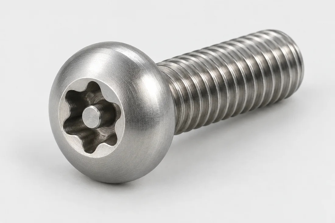
Specify the drive, not just its name
Pin-in six-lobe, five-lobe, Y-type, triangular and two-hole drives are different interfaces. Even similar-looking recesses may have different profiles. Supply a controlled drawing or matching tool specification, including recess depth, center-pin geometry and tolerances. A photograph can identify the general family, but cannot establish whether a production screw will fit the service tool.
Review service access in the installed housing
A security screw may be easy to drive on a bench but inaccessible inside a recessed enclosure. Include the housing recess, tool approach, driver diameter and permitted insertion depth. An enlarged flange can also interfere with a nearby wall. Review the assembled condition before fixing the head envelope, especially when a restricted drive is combined with a non-standard head.
Balance deterrence with maintenance
A special drive discourages casual removal; it does not provide an absolute security rating. Decide who needs service access and how replacement tools will be controlled. Consider whether the screw must remain captive when a panel is opened. These decisions affect the assembly and purchasing specification, rather than being solved by the drive recess alone.
Approve the production tool interface
Evaluate the intended driver with representative finished samples. Check engagement, seating and the agreed assembly behavior after any coating. Define visible-head appearance separately from functional recess acceptance. External profile screening does not demonstrate recess torque performance; use the agreed functional check and record the tool specification with the approved screw revision.
Review the route before fixing the quotation
For security & tamper-resistant screws, review Multi-Station Cold Heading, Secondary & Precision Operations, Coatings & Surface Treatments against the drawing and quantity. Identify which features can be produced in the initial shape and which require a separate setup. A change to a functional shoulder, bore, drive or thread can change the proposed route as well as the inspection effort.
The drawing review should resolve drive options; tool interface; head configurations. Keep material condition and finishing allowance attached to those requirements. Define the acceptance condition for critical features and approve any proposed dimensional change before comparing samples with the original assembly.
From drawing to approved samples
Provide the drive drawing or matching tool specification. Tamper resistance depends on tool availability and the complete assembly; it is not absolute security. Identify the drawing revision, prototype quantity and expected repeat demand. Where the first part is based on an existing sample, separately confirm material and hidden features rather than inferring them from appearance.
The typical sampling lead time, including tooling, is approximately 10–15 days. The schedule is confirmed after drawing review and agreement on the sample specification; material availability, special treatment and inspection requirements can affect the confirmed date. Confirm when the agreed schedule starts in the quotation. Sample approval and repeat-production delivery are separate milestones.