
 ZUFEK
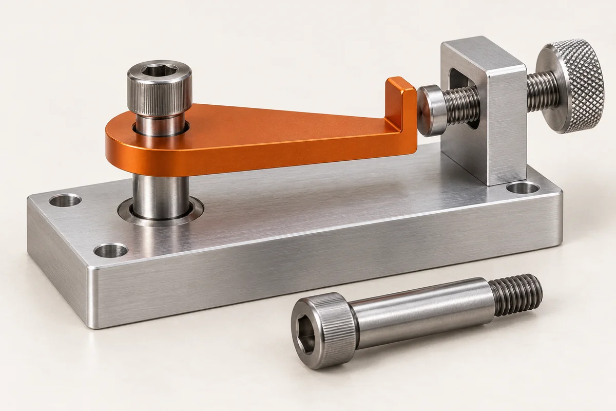
Project brief and operating concept
Develop a serviceable pivot-and-stop concept for an automation fixture. A shoulder screw retains a moving plate and provides its defined pivot surface; a separate knurled adjuster establishes a stop position. Keeping the two functions distinct allows pivot clearance and adjustment contact to be reviewed independently. This is an illustrative proposed project, with no claimed customer installation, tested cycle life or achieved positioning accuracy.
Define interfaces before dimensions
Obtain the moving plate, mating bore, mounting base and any washers or bushings in an assembly section. Identify the locating datum, required movement, operating range, contact surfaces and available tool access. The mechanism designer must establish loads, allowable play, duty cycle, wear and any guarding requirements. The screw alone does not establish the safety or accuracy of the fixture.
Shoulder diameter and axial stack
Define shoulder diameter against the mating bore and intended clearance. Define shoulder length from the seating face so tightening the screw retains the plate without unintentionally clamping its motion. Include all parts in the axial stack and the intended clearance. An excessively short shoulder can clamp the plate; an excessively long shoulder can leave unintended axial movement. Review the actual tolerance stack before releasing limits.
Transition, thread and service access
Provide clearance for the shoulder-to-thread transition and define usable engagement in the base. Check whether the tip can bottom in a blind hole before the screw seats. Keep the head and driver accessible through the permitted movement and service sequence. The thread class controls the threaded interface; it is not a substitute for the tolerance on the plain locating shoulder.
Adjustment screw and retention of setting
Select the knurled head envelope around finger clearance. Define the contact end, mating stop surface and required travel. Pitch describes nominal movement per turn, while the mechanism, thread fit and contact affect the actual setting. Establish a separate locking arrangement where the application requires retention under its operating conditions. Do not treat a fine thread or hand grip as proof of repeatability or vibration resistance.
Material and finishing review
Compare an appropriate steel or stainless solution against wear, exposure, mating material and the required final condition. If a controlled shoulder surface is coated, define the finished size and coverage. If the material is treated after machining, review possible dimensional change and whether finishing is needed afterward. Grinding is a possible route for specified size, form or texture; it is not mandatory simply because the product is a shoulder screw.
Sample route and repeat production
Review CNC turning for the initial compound geometry and local thread/relief features. A repeat-production alternative may begin with a cold-headed blank followed by precision secondary work. Cost and feasibility should include all local features, treatment, final finishing and inspection. When samples and production use different routes, agree what must be reconfirmed before transferring the approved design.
Inspection and functional trial
Check shoulder size and length, seating geometry, specified datum relationships and thread acceptance in the final supplied condition. CCD screening can address accessible external profile dimensions after the setup is validated. Surface texture, internal geometry and some datum relationships need complementary methods. In the assembly trial, examine full movement, intended axial clearance, access to the adjuster, contact at the travel limits and retention of the setting under the agreed conditions.
Sample approval and change loop
Agree the drawing, material, route and inspection plan before tooling and samples. Typical sampling including tooling is approximately 10–15 days, subject to review and confirmation. Compare the sample report with the approved requirements and document the mating-part trial. If binding or excess movement is observed, investigate the stack, transition, bore and final surface condition before changing one dimension in isolation. Reinspect affected features after a revision.
Release package and open requirements
Retain the approved assembly section, screw and adjuster drawings, material/final condition, finish coverage, inspection methods and sample decisions. Set the real load, life, travel, play and positional acceptance with the machine designer; no numerical performance is claimed here. Record the revision that passed the agreed trial before ordering repeat parts, and re-evaluate changes to the plate, bore or surface system.